Home ❯ Knowledge Base ❯ Assembly Manual ❯ Core One Setup Assembly (4/4)
CORE One Setup Assembly (4/4)
Step 34
We are going to attach the PTFE-tubes before further assembly.
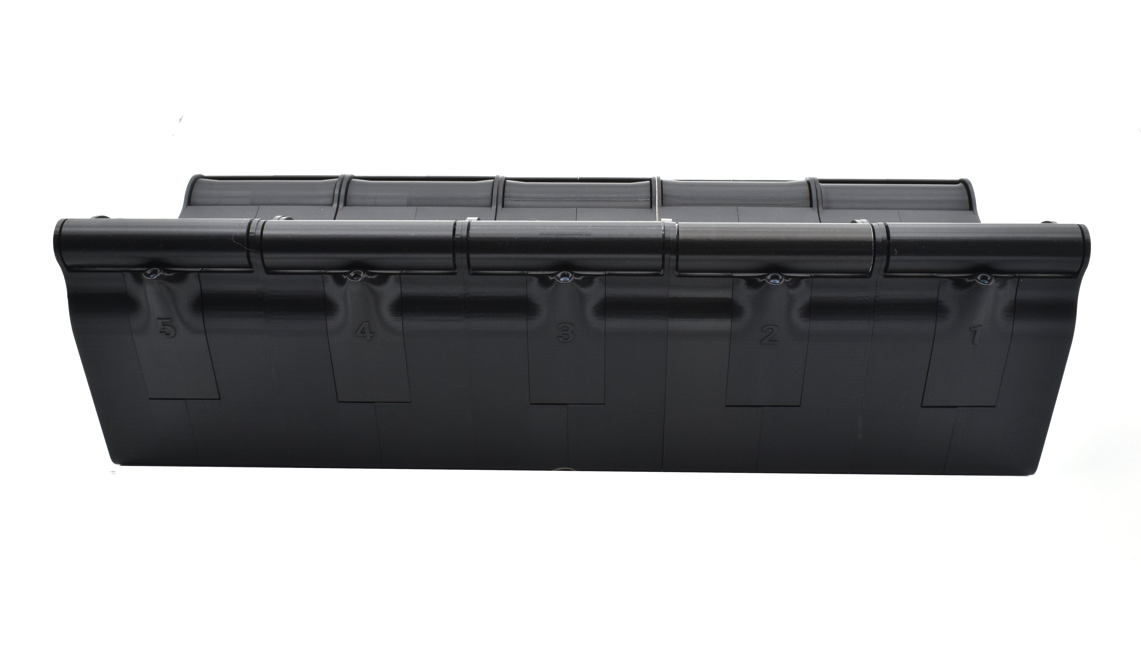
Each tube length corresponds to a certain PTFE-Guide number:
- 480mm Tube
- 410mm Tube
- 400mm Tube
- 410mm Tube
- 480mm Tube
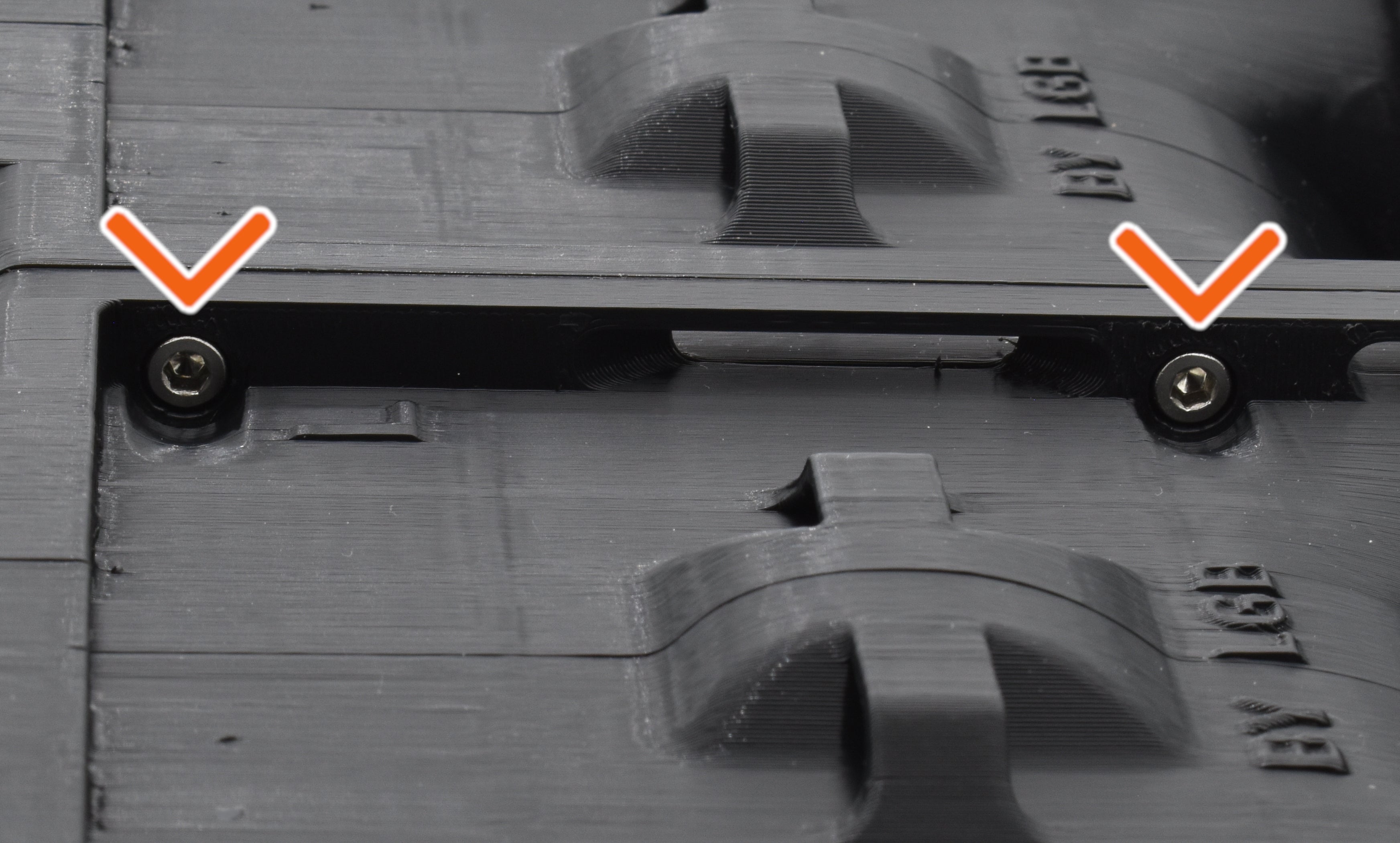
Insert a correct corresponding tube through the bottom hole of one of the modules (see picture). Make sure the tube is pushed all the way in.
Secure the tube in place with a M3x20 screw via the screw hole in the PTFE-Guide.
Repeat these steps for all modules.
Step 35
Before assembling the modules together, take a look at the bottom of the modules.
Note the screw holes underneath made for connecting the modules together (see picture).
Step 36
Connect the modules together with the M3x8 screws. Start with the module numbered 1 to the left, and connect the modules in ascending order according to the picture.
Step 37
Let's route the tube through the Rewindr.
There are multiple holes and slots that are for guiding the tubes. Use the picture as reference and route the tube out the back of the module.
Step 38
Prepare the following items:
- R-Side-panel (1x)
- L-Side-panel (1x)
- PTFE-Clamp (1x)
Step 39
Attach the R-Side-panel on the right side of the Rewindr.
Step 40
Repeat this on the other side with the L-Side-panel.
Step 41
Finally, snap the Rewindr onto the brackets on top of the CORE One.
Step 42
Connect the Rewindr's PTFE-tubes to the MMU3 according to the picture.
You may need to adjust the length of the tubes by cutting them.
⚠️ Be careful! Don't cut too much of the tubes off!
Attach the PTFE-clamp to the tubes according to the picture.
Step 43
Turn on the CORE One.
- Go to Settings and enable the MMU Unit
- Then, continue from Settings ❯ Hardware ❯ MMU, and change the Front PTFE Length to 750mm.
Step 44
Congratulations! You have now finished assembling the CORE One Rewindr Setup!
Continue to the last chapter: